...
Ensure that all four feature classes (streets, sidewalks, parking, buildings) appear in the Contents pane on the left. If you are missing any layers, drag them from the Catalog pane on the right directly into the Map view. The layers of the Rice campus should look familiar. If desired, update the symbology of each of the layers to a color of your choice by right-clicking on the color patch beneath each layer name and selecting a color. For example, you might choose to make the parking and streets layers two shades of gray, the sidewalks layer tan, and the buildings layer red.

Now you will add in a JPEG file depicting an aerial view of campus. This image is just like any other image file you are familiar with and does not contain any sort of spatial reference.
...
The full extent of the image now appears behind the current layers. It is always good to zoom in to the approximate extent of the image before using the Fit to Display command. Notice that while both layers are now visible, they are not yet perfectly aligned. If significant rotation or scaling was necessary to identify common control points, you would use the Move, Scale, and Rotate buttons on the Georeference tab. Once control points have been added, these tools are no longer available.
You now need to identify a common point in both the aerial image and the vector layers.
- In the Table of Contents, uncheck the parking and sidewalks layers to make the aerial image easier to view.
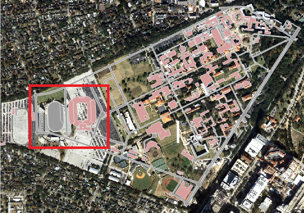
- Visually, identify the football stadium in both the aerial layer and the buildings layer.
Hold down Shift and your cursor should switch from a pointer finger to a magnifying glass with a plus sign.
Info If you don't see the proper cursor, then you may need to re-select the Explore button on the Map tab in the ribbon.
- On the western portion of campus, click and drag a box around the football stadium in both layers to zoom into the area in which you will add your first control point.
- In the ribbon, on the Georeference tab, click the Add Control Points button. Your cursor will change to a crosshair.
- Click on the southwest corner of the upper deck of the stadium in the aerial layer.
Info title Tip If your first click is on an unintended location, press Esc to remove the point. Then click the Add Control Points button again to resume adding a point.
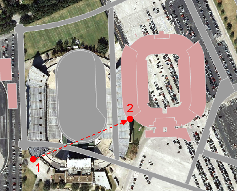
- With a line linking to the first point you clicked on, click on the southwest corner of the upper deck of the stadium on the buildings layer.
The two points will snap together, lining up the image at that particular control point.
| Info | ||
|---|---|---|
| ||
If your second click is on an unintended location or you clicked on the two points in the opposite order, then click |
- In the Table of Contents, right-click the streets layer and select Zoom to Layer to return to the full extent of the image.
At this point, the image is aligned at the one control point, but the scale of the image does not match the scale of the vector layers, so nothing else is yet aligned. You will need to select another control point to begin to establish the proper scale. Remember, it is best to select a point that is not horizontally or vertically in line with the existing control point.
- Visually, identify Fondren Library in both the aerial layer and the buildings layer.
- On In the Tools toolbarribbon, click the Zoom In Map tab and click the Explore button.
- In the center of campus, hold down Shift and click and drag a box around Fondren Library in both layers to zoom into the area in which you will add your second control point.
- In On the Georeferencing toolbarribbon, click the Georeference tab and click the Add Control Points button.
- Hold down the Spacebar to temporarily override snapping, so that you can accurately click Click on the southwest corner of Fondren Library in the aerial layer, without being forced to snap to the vector layers..
- With Release the Spacebar to reactivate snapping and, with a line linking to the first point you clicked on, click on on the southwest corner Fondren Library on the buildings layer.
The two points will snap together, lining up the image at that particular control point.
- In the Table of Contents, right-click the streets layer and select Zoom to Layer to return to the full extent of the image.
...
Notice that, in the northern-most section of campus, the buildings are not quite aligned. You will add a third control point in that area.
- Visually, identifyMartel College in both the aerial layer and the buildings layer.
- On In the Tools toolbarribbon, click the Zoom In button click the Map tab and click the Explore button.
- In the northern-most portion of campus, hold down Shift and click and drag a box around Martel College in both layers to zoom into the area in which you will add your third control point.
- In the Georeferencing toolbar, click the Add Control Points button.
- Hold down the Spacebar and click on the northwest corner of Martel College in the aerial layer.
- Release the Spacebar and, with a line linking to the first point you clicked on, click on the northwest corner Martel College on the buildings layer.
- In the Table of Contents, right-click the streets layer and select Zoom to Layer to return to the full extent of the image.
At this point, the image looks well aligned with the other vector layers.
- On the Georeferencing ToolbarIn the ribbon, on the Georeference tab, click the View Link Control Point Table button.
This table lists all the control points you have added. The residual, in the final column of the table, is a measure of how distorted the image has become. A lower residual indicates that the georeferenced image has less distortion from the original image. It not necessary to obtain a residual of zero, as this is difficult unless both layers are from the same source or were already in the same coordinate system.
If you added a poor or incorrect control point, you could select it in the table and click the Delete Link button to remove it. You could also simply uncheck it, so that it is no longer factored in to georeferencing calculations. You would then want to continue adjusting your control points until you achieved the desired result.
- Close the Link Table Map: aerial.jpg control point table view.
Notice that none of the final three control points are in line with each other vertically or horizontally, the image appears to be well aligned, and the residual is at or close to 0. These are all indications that the georeferencing was successful.
- When you are satisfied with your control points, in the ribbon, on the Georeferencing Georeference toolbar, click the Georeferencing drop-down menu and select Update Georeferencing either the Save button.
Notice that the control points have disappeared.
- On the Standard Above the ribbon, on the Quick Access toolbar, click the the Save button button.
- Close ArcMap ArcGIS Pro.
- On the desktopDesktop, double-click the ImageryTutorialData folder Imagery folder.
Before beginning this tutorial, there was only one aerial file: aerial.jpg. During the tutorial, you generated the three additional files. The JGWX file contains the spatial referencing information that you just created. Because this new file has been created, the image will now line up spatially whenever you add it into a new data frame. In other words, you only need to georeference a layer once.
...