...
- In the Table of Contents, uncheck the World imagery layer to turn it off.
- Click the Bookmarks menu and select the Tracts bookmark.
- In the ‘Create Features’ window, click the Tracts template.[GSA4]
This activates the Polygon construction tool , which you set as the default tool using the Template Properties. Since the tracts share an edge with the park boundary and an adjacent tract, you can use them to help you construct the shape of the polygon.
 - On the Feature Construction mini toolbar, ensure the Line construction method is selected.

With the Line construction method, a vertex is placed each time you click, with the segments between vertices being straight lines. - Snap to the corner of the Zion park boundary polygon symbolized in light green, so that the SnapTip reads “Zion park boundary: Vertex” and click once.
...

- Move your pointer up (to the north), snap to the corner of the tract and the park boundary, so that the SnapTip reads “Tracts: Vertex”, then click again.
You now have created two vertices with a straight line connecting them to define the eastern boundary of this tract. - On your map display, hover over the bottom-right corner of the existing tract above so the SnapTip ‘Tracts: Vertex’ appears. Right-click your mouse and click ‘Direction’ and hit Enter.
...

This will lock your next point to be on the bottom edge of the existing tract.- Right-click and select ‘Distance’ ‘Distance’ and type 2600. Ensure the units is set to ft and press Enter.
The buttons to choose a segment construction method on the Feature Construction toolbar are also found on the Editor toolbar, but it is often easier to access them on the Feature Construction toolbar since it is closer to your pointer. If you click a segment construction method on the Feature Construction toolbar, it then becomes active on the Editor toolbar, and vice versa. Two of the most common segment construction methods, Straight Segment and Endpoint Arc Segment, are located directly on the toolbar, but there is a palette to the right of these buttons containing additional methods.
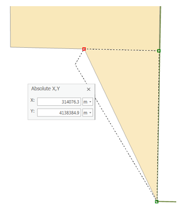
To enter the final measurement for the corner, you need to type a specific coordinate. - Right-click anywhere on the map and select Absolute X, Y….
Absolute XY allows you to type an exact x,y coordinate for the next vertex. By default, the values you enter are in map units, which are meters for this map. If you want to enter values in decimal degrees or other formats, you can click the arrow to change the input boxes
...
 Tip: If you make a mistake and want to cancel out of a sketch constraint, which is a command that limits the placement of the next vertex, you can press the ESC key. Once a vertex is added, you can delete it by pressing the Undo
...
- button
 on either the Feature Construction toolbar or the Standard toolbar.
 - For the ‘X:’ box, type “314076 “314076.3”3”.
- For the ‘Y:’ box, type “4138384 “4138384.9”9”.
- Press Enter to automatically create a new vertex in the specified location.
- On the Feature Construction mini toolbar, click the Finish Sketch button.
You have created the first polygon lot feature. You could also use the F2 key, double-click the map, or right-click to finish the sketch. - On the Map toolbar, click the Explore tool.

- On the Map Display, click the new feature you just created.
Notice that the attribute value for the Ownership field is Private, which is the default value you set in the template's properties. - Close the ‘Identify’ ‘Identify’ pop-up window.
Creating rectangular polygons
...
- On the Map toolbar, click the Explore tool tool
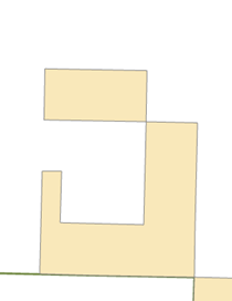
 and pan the map slightly to the west so the J-shaped polygon is centered in the display, as shown below.
 - In the ‘Create Features’ window, click the Tracts template, then the Rectangle tool,
 to make it the active construction tool.
 - Snap to the upper left corner of the J-shaped polygon, as shown below, and click to set the first corner of the rectangle.
...

...
- Right-click anywhere on the map and select Direction….
- Type “179” “179” (as in 179 degrees), and select the unit P, then press Enter.
This establishes the angle for the rectangle. As you move your pointer around the map, you see a rectangle preview of the feature. By default, angles are entered in degrees using the polar system, which is measured counterclockwise from the positive x-axis. You can specify a different direction measuring system or unit on the Editing Options dialog box > Units tab. - Right-click anywhere on the map and select Width….
- Type “400” “400” to set a width of 400 meters, which are the map units, and press Enter.
...
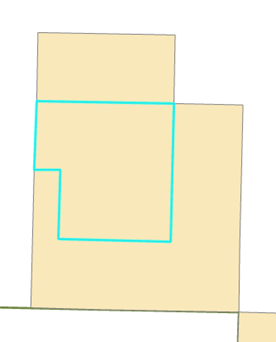
- Move your pointer up and to the left so the rectangle is created in the correct position in relation to the existing feature, as shown above.
- Right-click and select Height….
- Type “800” “800” to set a length of 800 meters and press Enter.
Creating adjoining polygons
You now need to create one more polygon to fill in the space between these two polygons. You could snap to every vertex, but an easier way is to use the Auto-Complete Polygon tool, which uses the geometry of existing polygons to create new adjacent polygons that do not overlap or have gaps.
- In the ‘Create Features’ window, click the Tracts template, then the Auto Complete Polygon tool
 to make it the active construction tool.
 - Snap to the lower left corner of the rectangle you just created and click.
- Move your pointer southward, snap to the corner of the original existing J-shaped polygon, as shown below, and click to add a vertex.
...

- On the Feature Construction mini toolbar, click the Finish Sketch button.

When using the Auto-Complete Polygon tool, ArcMap automatically uses the shapes of the surrounding polygons in that layer to create the geometry for the new polygon.
...
- On the Edit toolbar, click the Save button to save your edits.

- Click the Save button on the top-left of the window to save your map project.

The new features have been created with the default attribute values (Private) specified in the template. If you wanted to add other information, such as ID numbers, you would select the features and type the values into the ‘Attributes’ window.
Exercise 2
Exercise 2a: Defining new types of features to create
...