...
- Above your map display, click the 02 Creating Features map.
- In the Table of Contents, select the Research areas layer and open the Create Features window in the Edit toolbar.
- Click the Manage Templates icon
 and select the Research_areas feature class from the list, under 02 Creating features.
 - In the lower menu, click the New drop-down menu and select Template...
The ‘New Template’ window opens. - In the ‘Name:’ box, type “Buffer zones” “Buffer zones”.
- In the ‘Description:’ box, type “Buffer “Buffer zones around Zion research areas”areas”.
- Select the Attributes tab from the left panel, and type “Buffer zone” “Buffer zone” next to the name field.
This will automatically populate the Name field of every feature you create with this template with “Buffer zones” - Click OK.
A new feature template has been created. - Notice that the ‘Create Features’ window lists a new feature template for the Buffer zones.
...
Editing commands that create new features automatically from existing features, such as Buffer, require you to choose the feature template to use when creating the new feature. Similar to clicking a feature template in the Create Features window, choosing a template on these dialog boxes defines the layer where a feature will be stored and the default attributes for the new feature. A buffer feature can be created as either a line or a polygon, so you could see both line and polygon templates listed but no templates for any other types of features.
- Click the Bookmarks menu and select the Research areas bookmark.
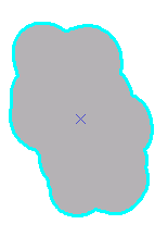
The map zooms to the Goose Creek area of the park. The polygons depict research-only areas. - In the Table of Contents, uncheck the Streams layer to turn it off.
This makes it easier for you to see and select the correct features. - On the Edit toolbar, click the Select tool.

- Select the southernmost Research areas polygon—the tan-colored one, as shown below.
...

- On the Edit toolbar, select Modify from the Features group.
This will open up the Modify Features window, which has a list of all the available tools. - Select Buffer from the Construct tools group.
- Select Buffer zones from the Template drop-down list.
The Select Feature Template window shows only templates that are valid output types for the particular command rather than all the templates listed on the Create Features window. In the case of Buffer, polygon and line templates would be listed, if available, since both these geometry types can store the new buffer feature. On the other hand, when using a command, such as Copy Parallel, that creates line features, only line feature templates are listed for that command. If you want to find a template by name, you can enter it into the <Search> box. - Next to ‘Buffer Distance’ type “300” “300” and select m instead of the default ft.
This means a buffer will be created 300 meters (the map units) from the border of the selected polygon.
...

Click Buffer.
...
The new 300-meter polygon buffer feature is created using the properties of the Buffer zones feature template. The new feature is selected and is drawn on top of the existing feature.
...
- On the Edit toolbar, click the Select tool.

- Click the center of the buffer feature.
Since there are multiple selectable features where you clicked, the selection chip may appear near where you just clicked. - Click the arrow to the right of the selection icon to view a list of the features from which you can select.

Features are listed in the selection chip by their display expression, which is set on the Layer Properties > Display tab.
...

- Rest your pointer over any feature in the list to flash it on the map.
- Click the Isolated Mesa Tops feature to select it.
You will use this feature to clip a hole in the Buffer zone polygon. The Clip command only clips polygon features that are within a buffer distance of a selected feature—in this case, the Isolated Mesa Tops research area. - Open the Modify Features window and select Clip from the Divide group.

- Ensure the ‘Buffer Distance:’ is 0.
This way, you will be clipping to the exact border of the selected feature rather than at a distance from it.
...
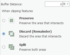
- Click Discard the area that intersects.
This removes the overlapping area from the feature that is being clipped. - Click Clip.
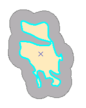
The overlapping area is clipped and now the original Research areas feature is visible through the hole in the buffer feature.
...
Since the buffer feature has a hole in it, its geometry is represented in ArcGIS as a multipart polygon. Multipart features either contain holes in them or are composed of more than one physical part that only references one set of attributes. For example, the individual islands that make up Hawaii are often represented as a multipart polygon feature.
Cutting a polygon
The neighboring research area needs to be divided into two polygons based on the river that runs through the middle. You can use the Cut Polygons tool to split the polygon.
...
- On the Edit toolbar, click the Select tool.

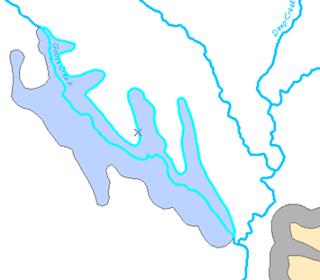
- Click the Goose Creek research area, the blue polygon just to the west of the polygons you were previously editing. You may need to zoom in or pan to this feature so you can see it better.
- In the Table of Contents, check the box to the left of the Streams layer to make the streams visible again so you can trace along them.
- On the Snapping drop-down menu, select Intersection Snapping.
This turns on snapping to intersections between features, which will help you ensure that the line used to cut the polygon starts and stops at the intersection of the polygon and line edges. - On the Edit toolbar, click the Split tool.

- On the Feature Construction mini toolbar, click Trace.

- Snap to the intersection of the polygon edge and the stream line nearest the buffer polygon you previous created, as indicated below, then click to start tracing the line through the polygon. Follow along the stream line to trace it.
You may need to zoom in to snap to the correct point.
...

Once you have traced all the way across the polygon, snap to the intersection of the polygon and the stream line at the northern edge of the polygon, and click the map to place a vertex, as shown below.
...

- Right-click anywhere on the map and select Finish Sketch.

You are finishing the sketch used to cut the polygon. The polygons flash on the map as the cut is made and the new features are selected. If an error occurs, ensure that you have the correct feature selected, try the trace again, then make sure your line goes completely across the polygon. It may help to zoom in when you start and end the trace.
...

On the Editor toolbar, click the Select tool.

- Click each new feature and notice that you now have two polygons.
...
- On the Edit toolbar, click Save.
In this exercise, you learned how to clip polygons and split them by tracing along an overlapping line feature.
...
- Above your map display, click the 03 Editing Features map.
- Click the Bookmarks drop-down menu on the Map toolbar and select the Trail bookmark.
- Click the Edit toolbar and click the Select tool.
- Select the trail line (the brown and gray dashed line) that connects to the road.
- On the Edit toolbar, click the Vertices tool.

When you are viewing the sketch geometry of a feature, the Edit Vertices toolbar appears, giving you quick access to commands used when editing a feature's vertices and segments.
...

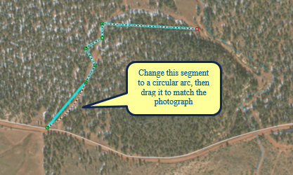
When compared to the aerial photograph, notice that this line is straight when it should be curved, and it also has some extra vertices. You can easily change a straight segment into a circular arc or Bézier curve, and vice versa, and delete the extra vertices. A Bézier curve is smooth and has on each of its two endpoints handles that can be moved to change the direction and the steepness of the curve. You can create Bézier curves by digitizing them using the Bézier Curve sketch construction method or by using certain editing commands, such as Smooth on the Advanced Editing toolbar.- Move Move your pointer over the middle of the trail line segment closest to the road, as shown below, and notice that the pointer changes to indicate you are working with a segment.
- Right-click the middle of the trail line segment and selectChange Segment > Circular Arc.
The segment changes to an arc. - Click, drag, and drop the arc over the trail on the aerial photograph. You can hold down the SPACEBAR key to turn off snapping temporarily if you are having difficulty placing the curve where you want it, because it is snapping to its original location.
...
- Click the map away from the new line feature to update its shape.
- Double-click the trail line feature, which accomplishes the same thing as using the Edit Vertices button.
- On the Edit Vertices mini toolbar, click the Delete Vertex tool.

- Draw a circle around the three vertices that form a zigzag shape between the previous segment and the horizontal segment, as shown below.
This deletes those vertices, as they are in the incorrect locations and are not needed to maintain the shape of the line in this area.
...

...
- On the Edit Vertices toolbar, click the Normal Vertices tool
 (the white Edit tool).
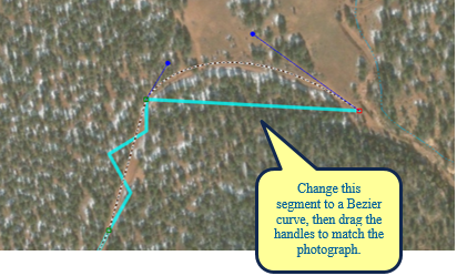
This allows you to continue working with the segments and vertices. - Right-click the northernmost trail line segment and selectChange Segment > To Bézier Curve.
A new set of Bézier curve handles is added, and the segment changes into an S-shaped curve. You can see the locations of the vertices and handles, which are displayed in blue. - Rest your pointer over a green vertex, then rest it over a blue handle.
You get different pointer icons depending on the type of point you are over. - Drag the blue handles to reshape the curve to match the aerial photograph, as shown below.
...
- Click the map away from the trail line feature to update the changes to its shape.
If you need to refine the line's shape further, double-click it again with the Edit tool and modify the segments. If you want to insert or delete a vertex, use the tools on the Edit Vertices toolbar.
...

- On the Edit toolbar, click Save.

- You changed segments into different types and edited vertices
...
[GSA1]There is no project file in the folder
[GSA2]It’s saying there are no editable layers (the Ranger stations layer is read only)
[GSA3]Also not editable
...
- .