...
Now you will delineate the watershed that flows to the outlet point.

- At the bottom of the Create Features pane, click the Geoprocessing tab.
- At the top top left of the Geoprocessing pane, click the Back button.
- In the search box, type "watershed".
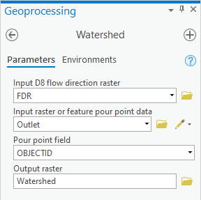
- Click the Watershed Watershed (Spatial Analyst Tools) tool.
- For ‘Input D8 flow direction raster’, select the FDR layer raster.
- For ‘Input raster or feature pour point data’ select the Outlet layer.
- For ‘Output raster’, rename the raster from “Watersh_FDR1” to “Watershed”.
- Ensure your Geoprocessing pane appears as shown below and click Run.

- In the Contents pane, right-click the Watershed layer and select Zoom To Layer.

Notice that this You can toggle the Subbasin_StatePlane layer on and off. Notice that the watershed boundary you have created is very close, but does not exactly match the boundaries of the subbasin you were originally provided from NHDPlus.
...
- At the top left of the Geoprocessing pane, click the Back button.
- In the search box, type "calculator".
- Click the Raster Calculator Calculator (Spatial Analyst Tools) tool.
- Using the same clicking technique as before, enter the following equation: ("FAC" > 3000) & ("Watershed" > 0).
- For ‘Output raster’, rename the raster from “fac_rasterca” to “Streams”.
- Ensure your Geoprocessing pane appears as shown below and click Run.

...

Again you should have a binary raster, where flowline cells are assigned a value of 1 and all other cells are assigned a value of 0.
...
- At the top left of the Geoprocessing pane, click the Back button.
- In the search box, type "stream".
- Click the Stream Link tool.
- For ‘Input stream raster’, select the Streams layer raster.
- For ‘Input flow direction raster’, select the FDR layer raster.
- For ‘Output raster’, rename “StreamL_Stre1” to “StreamLinks”.
- Ensure your Geoprocessing pane appears as shown below and click Run.


- Symbolize the StreamLinks layer using unique values.
- In the Contents pane, collapse the StreamLinks symbology.
...
Now you will delineate the catchment basin associated with each stream link. These catchment basins are similar to the subwatersheds you downloaded from NHDPlus.
- Return to the Geoprocessing pane.
- At the top left of the Geoprocessing pane, click the Back button.
- In the search box, type "watershed".
- Click the Watershed Watershed (Spatial Analyst Tools) tool.
- For ‘Input D8 flow direction raster’, select the FDR layer raster.
- For ‘Input raster or feature pour point data’ select the StreamLinks layer.
- For ‘Output raster’, rename “Watersh_FDR2” to “CatchmentsCatchmentsRaster”.
- Ensure your Geoprocessing pane appears as shown below and click Run.


- Symbolize the Catchments CatchmentsRaster layer using unique values.

- In the Contents pane, collapse the Catchments CatchmentsRaster symbology.
Converting rasters to features
Now you will convert the Catchments CatchmentsRaster raster into a polygon feature class.
- Return to the Geoprocessing pane.
- At the top left of the Geoprocessing pane, click the Back button.
- In the search box, type "raster to polygon".
- Click the Raster to Polygon tool.
- For ‘Input raster’, select the Catchments layer.
- For ‘Output polyline features’, rename “RatsterT_Catchme1” to “CatchmentPoly”.
- Uncheck Simplify polylines.
- Ensure your Geoprocessing pane appears as shown below and click Run.

- Symbolize the CatchmentPoly layer using unique values with ID as the value field.

- In the Contents pane, collapse the CatchmentPoly symbology.
...