...
- On the Desktop, double-click the Computer icon → gisdata (\\fon-gis04file-rnas.rice.edu) (OZ:) → > Short_Courses → Bringing_Data_Into_ArcGIS_Series → > Creating_Vector_Data.
- To create a personal copy of the tutorial data, drag the Editing folder onto the Desktop.
- Close all windows.
Exercise 1
Exercise 1a: Creating new points
Opening an existing project
In this exercise, you will use an aerial photograph to create a new point feature representing a park ranger station in Zion National Park. Once the feature is created, you will then add attribute values to the point. You are introduced to the Editor toolbar, the Create Features pane, and the Attributes pane, which are the main elements of the ArcGIS Pro user interface when editing.
- On the Desktop, double-click the ArcGIS Pro icon.
- Click Open an existing project….
- In the ‘Open’ dialog box, click the Browse button.
- Navigate to the Editing folder on the Desktop.
- Select Vector_data.aprx and click OK to open the project file.
...

Since you are creating points, clicking the map once adds the feature. If you were drawing lines or polygons, however, you would need to use more than one click so you could create segments in between vertices. Notice that the center of the symbol is highlighted with a solid, cyan color (light, bright blue). By default, as soon as you create new features when editing, they are selected. This allows you to easily identify the new feature and add attribute values to it.
7. On the Edit toolbar, in the Selection Group, click the Attributes button. 
...
12. To stop creating new features, close the Create Features pane and click the Explore button on the Map toolbar in the Navigate group.
...
- Click the Map toolbar tab and click the Bookmarks menu to select the Digitizing roads bookmark.
The extent is just south of the point feature you created in the previous exercise. - On the Edit toolbar, click the Snapping pull-down menu and click the Snap icon to ensure that snapping is on (highlighted).
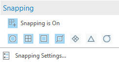
- Look on the Snapping drop-down menu and confirm that End
 , Vertex
  , and Edge
  snapping types are active. When enabled, the buttons are highlighted with a blue square. If they are not enabled, click each button to enable those agents.
 - Click the Snapping pull-down menu and select Snapping Settings…
From this dialog box, you can specify settings for snapping in ArcGIS Pro. - Ensure the XY tolerance is at least 10 pixelsPixels.
The snapping tolerance is the distance within which the pointer or a feature is snapped to another location. If the element being snapped to—such as a vertex or edge—is within the distance you set, the pointer automatically snaps to the location. - Click OK to close the Snapping Settings dialog box.
...
You are now ready to begin digitizing the new road.
- On the Edit toolbar, in the Features group, click the Create button.
- In the ‘Create Features’ pane, click the Local road line template, which is grouped under the Roads layer. This feature template was created for you and saved in the tutorial map document.
The list of available construction tools at the bottom of the pane changes to those used to create lines. Since the Line tool is the default tool for this template, it is activated automatically. - Rest your pointer over the endpoint of the existing line in the western portion of the map display, as indicated below, but do not click yet. Notice that the pointer icon changes to a square snap symbol and a SnapTip appears with the name of the layer (Roads) and the snap type (Endpoint) in use. You can zoom or pan closer if you need to do so.
- Click once on the Roads: Vertex.
...
- In the ‘Create Features’ pane, click the Manage templates button to the right of the search bar.
- Select the Tracts feature classlayer under Exercise1, and then select the Tracts feature template in the bottom half of the Manage Templates pane and click Properties.

This opens the ‘Template Properties: Tracts’ window. - In the ‘Description:’ box, type “Private lands in Zion”. The description appears when you rest your pointer over a template in the ‘Create Features’ window.

You can also use tags to identify and help search for templates in the future. A tag representing the layer type—Polygon—is added automatically. - Click in the ‘Tags:’ box immediately after “Polygon”, type “; Zion; landownership”.
Ensure that there is a semicolon and a space between each tag. - Under the Tools tab, ensure that ‘Polygon Tool (Default Tool)’ is selected and turned on. If it is not, check the circle next to it.
This ensures that the Polygon tool activates each time you choose the Tracts template. - Under the Attributes tab, click the hover over the ‘Ownership’ field in the grid. System information about the field is listed at the bottom of the dialog box.
- To the right side of the ‘Ownership’ field, click the blank space or <Null> value to clear the text and type “Private”, which will assign the attribute value Private.
This sets Private as the default attribute value for that field for all new features created with this template.
- Click OK.
- Click the Create Features icon on the top-right of the Manage Templates window to return to creating features.

...
- In the Table of Contents, uncheck the World imagery layer to turn it off.
- Click the Bookmarks menu and select the Tracts bookmark.
- In the ‘Create Features’ window, click the Tracts template.
This activates the Polygon construction tool , which you set as the default tool using the Template Properties. Since the tracts share an edge with the park boundary and an adjacent tract, you can use them to help you construct the shape of the polygon.
 - On the Feature Construction mini toolbar, ensure the Line construction method is selected.

With the Line construction method, a vertex is placed each time you click, with the segments between vertices being straight lines. - Snap to the corner of the Zion park boundary polygon symbolized in light green, so that the SnapTip reads “Zion park boundary: Vertex” and click once.

- Move your pointer up (to the north), snap to the corner of the tract and the park boundary, so that the SnapTip reads “Tracts: Vertex”, then click again.
You now have created two vertices with a straight line connecting them to define the eastern boundary of this tract. - On your map display, hover over the bottom-right corner of the existing tract above so the SnapTip ‘Tracts: Vertex’ appears. Right-click your mouse and click ‘Direction’ and hit Enter.

This will lock your next point to be on the bottom edge of the existing tract. - Right-click and select ‘Distance’ and type 2600. Ensure the units is set to ft and press Enter.
The buttons to choose a segment construction method on the Feature Construction toolbar are also found on the Editor toolbar, but it is often easier to access them on the Feature Construction toolbar since it is closer to your pointer. If you click a segment construction method on the Feature Construction toolbar, it then becomes active on the Editor toolbar, and vice versa. Two of the most common segment construction methods, Straight Segment and Endpoint Arc Segment, are located directly on the toolbar, but there is a palette to the right of these buttons containing additional methods.
To enter the final measurement for the corner, you need to type a specific coordinate. - Right-click anywhere on the map and select Absolute X, Y….
Absolute XY allows you to type an exact x,y coordinate for the next vertex. By default, the values you enter are in map units, which are meters for this map. If you want to enter values in decimal degrees or other formats, you can click the arrow to change the input boxes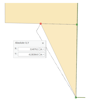
 Tip: If you make a mistake and want to cancel out of a sketch constraint, which is a command that limits the placement of the next vertex, you can press the ESC key. Once a vertex is added, you can delete it by pressing the Undo button
  on either the Feature Construction toolbar or the Standard toolbar.
 - For the ‘X:’ box, type “314076.3”.
- For the ‘Y:’ box, type “4138384.9”.
- Press Ensure the units are set to m and press Enter to automatically create a new vertex in the specified location.
- On the Feature Construction mini toolbar, click the Finish Sketch button.

You have created the first polygon lot feature. You could also use the F2 key, double-click the map, or right-click to finish the sketch. - On the Map toolbar, click the Explore tool.

- On the Map Display, click the new feature you just created.
Notice that the attribute value for the Ownership field is Private, which is the default value you set in the template's properties. - Close the ‘Identify’ pop-up window.
...
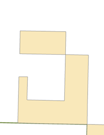
- On the Map toolbar, click the Explore tool
 and pan the map slightly to the west so the J-shaped polygon is centered in the display, as shown below.
 - In the ‘Create Features’ window, click the Tracts template, then the Rectangle tool,
 to make it the active construction tool.
 - Snap to the upper left corner of the J-shaped polygon, as shown below, and click to set the first corner of the rectangle.

- Right-click anywhere on the map and select Direction….
- Type “179” (as in 179 degrees), and select the unit P, then press Enter.
This establishes the angle for the rectangle. As you move your pointer around the map, you see a rectangle preview of the feature. By default, angles are entered in degrees using the polar system, which is measured counterclockwise from the positive x-axis. You can specify a different direction measuring system or unit on the Editing Options dialog box > Units tab. - Right-click anywhere on the map and select Width….
- Type “400” to set a width of 400 meters, which are the map units, and press Enter.
- Move your pointer up and to the left so the rectangle is created in the correct position in relation to the existing feature, as shown above.
- Right-click and select Height….
- Type “800” to set a length of 800 meters and press Enter.
...
- Click the Bookmarks menu and select the Research areas bookmark-only area bookmark.
The map zooms to the Goose Creek area of the park. The polygons depict research-only areas. - In the Table of Contents, uncheck the Streams layer to turn it off.
This makes it easier for you to see and select the correct features. - On the Edit toolbar, click the Select tool.

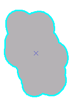
- Select the southernmost Research areas polygon—the tan-colored one, as shown below.

- On the Edit toolbar, select Modify from the Features group.
This will open up the Modify Features window, which has a list of all the available tools. - Select Buffer from the Construct tools group.
- Select Buffer zones from the Template drop-down list.
The Select Feature Template window shows only templates that are valid output types for the particular command rather than all the templates listed on the Create Features window. In the case of Buffer, polygon and line templates would be listed, if available, since both these geometry types can store the new buffer feature. On the other hand, when using a command, such as Copy Parallel, that creates line features, only line feature templates are listed for that command. If you want to find a template by name, you can enter it into the <Search> box. - Next to ‘Buffer Distance’ type “300” and select m instead of the default ft.
This means a buffer will be created 300 meters (the map units) from the border of the selected polygon.
Click Buffer.
...