...
- On the Desktop, double-click the Computer icon → gisdata (\\fon-gis04file-rnas.rice.edu) (OZ:) → > Short_Courses → Bringing_Data_Into_ArcGIS_Series → > Creating_Vector_Data.
- To create a personal copy of the tutorial data, drag the Editing folder onto the Desktop.
- Close all windows.
...
- On the Map toolbar, click the Explore tool
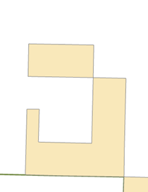
 and pan the map slightly to the west so the J-shaped polygon is centered in the display, as shown below.
 - In the ‘Create Features’ window, click the Tracts template, then the Rectangle tool,
 to make it the active construction tool.
 - Snap to the upper left corner of the J-shaped polygon, as shown below, and click to set the first corner of the rectangle.

- Right-click anywhere on the map and select Direction….
- Type “179” (as in 179 degrees), and select the unit P, then press Enter.
This establishes the angle for the rectangle. As you move your pointer around the map, you see a rectangle preview of the feature. By default, angles are entered in degrees using the polar system, which is measured counterclockwise from the positive x-axis. You can specify a different direction measuring system or unit on the Editing Options dialog box > Units tab. - Right-click anywhere on the map and select Width….
- Type “400” to set a width of 400 meters, which are the map units, and press Enter.
- Move your pointer up and to the left so the rectangle is created in the correct position in relation to the existing feature, as shown above.
- Right-click and select Height….
- Type “800” to set a length of 800 meters and press Enter.
...
- Click the Bookmarks menu and select the Research areas bookmark-only area bookmark.
The map zooms to the Goose Creek area of the park. The polygons depict research-only areas. - In the Table of Contents, uncheck the Streams layer to turn it off.
This makes it easier for you to see and select the correct features. - On the Edit toolbar, click the Select tool.

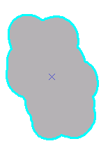
- Select the southernmost Research areas polygon—the tan-colored one, as shown below.

- On the Edit toolbar, select Modify from the Features group.
This will open up the Modify Features window, which has a list of all the available tools. - Select Buffer from the Construct tools group.
- Select Buffer zones from the Template drop-down list.
The Select Feature Template window shows only templates that are valid output types for the particular command rather than all the templates listed on the Create Features window. In the case of Buffer, polygon and line templates would be listed, if available, since both these geometry types can store the new buffer feature. On the other hand, when using a command, such as Copy Parallel, that creates line features, only line feature templates are listed for that command. If you want to find a template by name, you can enter it into the <Search> box. - Next to ‘Buffer Distance’ type “300” and select m instead of the default ft.
This means a buffer will be created 300 meters (the map units) from the border of the selected polygon.
Click Buffer.
...