...
- At the top left of the Geoprocessing pane, click the Back button.
- In the search box, type "stream".
- Click the Stream Order tool.
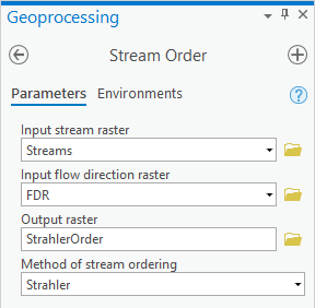
- For ‘Input stream raster’, select the Streams raster.
- For ‘Input flow direction raster’, select the FDR raster.
- For ‘Output raster’, rename the raster from “StreamO_Stre1” to “StrahlerOrder”.
- Ensure your Geoprocessing pane appears as shown below and click Run.
- In the Contents pane, turn off all layers except for the new StrahlerOrder layer, so that its symbology is more apparent.

...
- At the top left of the Geoprocessing pane, click the Back button.
- In the search box, type "zonal statistics".
- Click the Zonal Statistics as Table toolTable (Spatial Analyst) tool.
- For ‘Input raster or feature zone data’, select the StreamLinks layer from the drop-down menu.
- Use the For ‘Zone field’ drop-down menu to , select the Value field.
- For ‘Input value raster’, select the StrahlerOrder layer from the drop-down menu.
- For ‘Output table’, rename the table from “ZonalSt_StreamL1” to “OrderTable”.
- Ensure your Geoprocessing pane appears as shown below and click Run.

...
- In the attribute table, right-click on the StrahlerOrder field header and select Calculate Field.
- Scroll down the list of ‘Fields:’ and double-click the OrderTable.MINORITY field and click Run.
- Scroll down the newly populated StrahlerOrder field and notice the values of 1, 2, and 3 corresponding to Strahler order value. You no longer need join.
- Again, click the Table Options button and select Joins and Relates > Remove Join(s) > Remove All Joins.
- Symbolize the DrainageLines layer using graduated symbols based on the StrahlerOrder field.
- In the Contents pane, turn on only the Outlet, DrainageLines, and CatchmentPoly, layers and turn off all other layers.

...